
Operational amplifiers, or op amps for short, are useful integrated circuits that may be used for various purposes. They are common in the computer industry and can be combined in different op amp configurations to perform the desired action of the user.
Of course, to properly use these electrical components, people should know what op amp circuit configuration is this they’re handling. These op amps can come as inverting or non-inverting op amps, as well as other common configurations.
Table of Contents
Basics of Op Amps
An op amp is an integrated circuit that amplifies the input voltage, with its output determined by the components the op amp is connected to. Generally, the schematic diagram of an op amp would look like this:
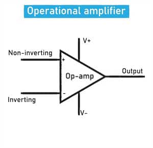
The op amp has two inputs – the non inverting (+) voltage and the inverting (-) voltage. It normally has one output (though two outputs exist as well). The op amp is powered by two terminals (V+ and V-, but some schematic diagrams may remove this).
An op amp has the following characteristics:
- An ideal op amp has no current flowing through the input. It has an infinitely large resistance (others would like to use the term “impedance”).
- It’s gain () can be expressed when the op amp is an open loop or closed loop.
- An open loop is when the op amp has no negative feedback. A practical op amp can have an open gain of as much as 1,000,000.
- However, practical op amps will need negative feedback with a resistance, and thus is in a closed loop when used. The closed loop gain is reduced compared to the open loop gain.
- An op amp may have output resistance that is internal to the IC, but the negative feedback reduces this output resistance to an insignificant amount.
- The output voltage may differ from the supply voltage by 1-3 volts. The output might get clipped if it goes beyond this.
- Ideally, an op amp has a large gain across all frequencies. But, in actual use, op amps tend to plateau their output around higher frequencies and decrease somewhere around -3dB.
Basic Op Amp Configurations
The most common op amp circuits are the inverting and non-inverting kinds. Other types of op amp circuits exist, but we’ll start with these two.
When doing op-amp circuit analysis to analyze the gain, we have to follow some rules:
- With regular outputs, the input pins have zero voltage difference.
- Because an ideal op amp has infinite resistance, no current is drawn from the input terminals.
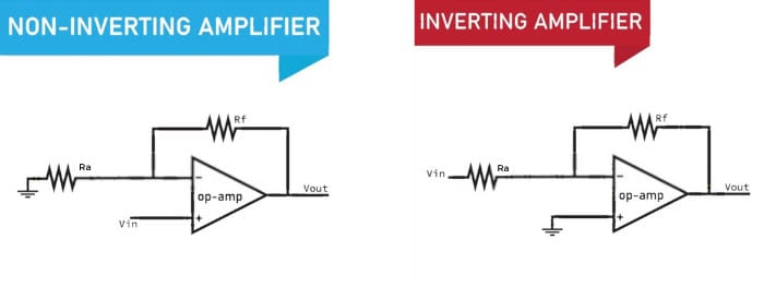
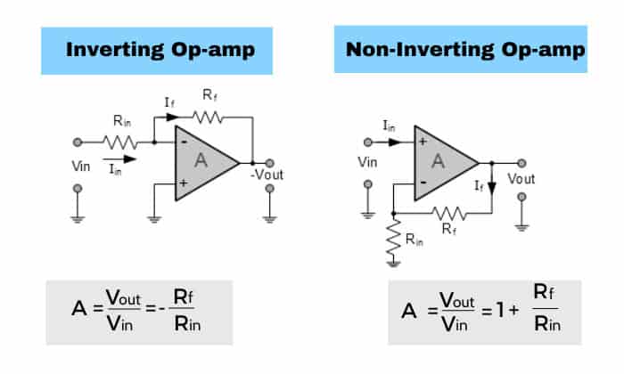
The first common op amp configuration is the non-inverting amplifier. It is an op amp where the input signal is applied to the non inverting (+) input terminal. The output of a non-inverting amplifier is non-inverted.
In our schematic diagram for the non-inverting amplifier, and make a voltage divider. Thus the op-amp gain formula and output voltage for this amplifier is:
\begin{equation}
A=\frac{R_f}{R_a}+1
\end{equation}
\begin{equation}
V_{out} = V_{in} \left(\frac{R_f}{R_a} + 1\right)
\end{equation}
The second common op amp configuration is the inverting amplifier. It is an op amp where the input signal is applied to the inverting (-) input terminal. The output of an inverting amplifier is inverted.
For the inverting op amp, the schematic diagram shows that if a current flows through, it will be the same current that flows through (that current cannot flow through the op amp since it has infinite resistance). Thus, the op-amp gain formula and the voltage formula can be derived to be:
\begin{equation}
A = -\frac{R_f}{R_a}
\end{equation}
\begin{equation}
V_{out} = -V_{in} \frac{R_f}{R_a}
\end{equation}
Other Op Amp Configurations
Aside from the two basic amplifier circuits, other configurations exist. These have different op amp equations based on their properties. Here is a summary of these configurations.
| Amplifier | Diagram | Op amp voltage equations |
| Voltage follower – very useful as a buffer | 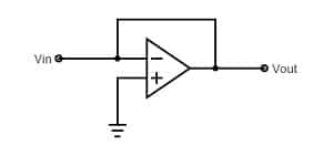 |
Technically no gain since: |
| Summing amplifiers | ||
| Non inverting summing op amp – combines two input voltages in the non inverting input | 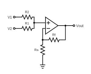 |
Only two resistors may be used for the positive pins |
| Inverting summing op amp | 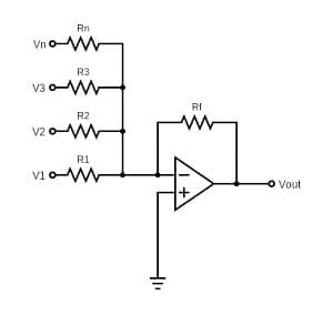 |
More than two resistors can be placed in the inverting terminal |
| Differential op amp | 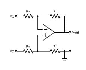 |
Produces an output proportional to the voltage difference between the two inputs |
| Integrator op amp | 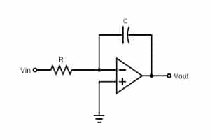 |
Uses a capacitor in the negative feedback
Produces an output based on RC time constants R and C Great for square wave inputs to make triangular outputs through integration |
| Differentiator op amp |  |
Swapped locations of capacitor and resistor compared to an integrator op amp
Produces an output based on the rate of change of the input Great for triangular wave inputs to make square wave outputs through differentiation |
Frequently asked questions
How do you identify an op-amp?
An op amp generally has two inputs and one output. It usually has five terminals: 2 input terminals, 2 power supply terminals, and one output.
In a schematic diagram, an op amp would look like a triangle with two inputs (+ and -) and one output.
What are the different configurations of op-amp?
Basic op amp circuits include the non inverting and inverting op amps. Other configurations include summing and differential op amps, as well as integrator and differentiator op amps.
Can I use an op amp as a voltage comparator?
An op-amp comparator is possible. It is an op amp that produces an output by comparing the two inputs and seeing which input terminal has a greater value. However, standalone voltage comparators exist and have better responsiveness than an op amp comparator.
Conclusion
A variety of operational amplifiers are available and have different functions for your needs. Looking at the schematic diagrams of basic or more complex op amps and analyzing them will help you understand op amp circuits problems and solutions.
Moreover, you’ll know what op amp circuit configuration is this.

I am Edwin Jones, in charge of designing content for Galvinpower. I aspire to use my experiences in marketing to create reliable and necessary information to help our readers. It has been fun to work with Andrew and apply his incredible knowledge to our content.